Dariusz on Software

Methods and Tools

About This Site

Software development stuff

Archive

Entries tagged "design".

Mon, 20 Jul 2009 05:12:58 +0000

Idealny projekt

Jakiś czas temu spotkałem się ze stwierdzeniem, że każdy system informatyczny który nie jest odpowiednio zaprojektowany przed rozpoczęciem prac programistycznych jest z góry skazany na "zatarcie się" w ciągu dwóch lat (znaczny wzrost kosztu wprowadzania zmian, "wypalanie się" zespołu). Programista, który te słowa wypowiedział (a z którym mam przyjemność pracować nad jednym z systemów), hołduje zasadzie, że najbezpieczniej jest zaprojektować wszystkie możliwe rozszerzenia systemu na początku, dzięki czemu unika się kosztownego procesu refaktoryzacji. Jeśli zaś znajdziemy się w sytuacji kiedy prace już ruszyły to nie ma już nadziei na płynny rozwój systemu.

Takie podejście do tworzenia systemów trąci aż zanadto metodą Waterfall (model kaskadowy), gdzie kolejne etapy powstawania systemu są uszeregowane w czasie (wymagania, projekt, implementacja, testy). Istnieje w nim ukryte założenie, że jest możliwe nieomylne wyznaczenie pełnych celów i zadań systemu na początku oraz zaprojektowanie odpowiedniej struktury która te cele i zadania spełni. Właśnie: założenie nieomylności jest chyba najtrudniejsze do spełnienia.

Dlaczego niektórzy programiści wierzą w idealny projekt? Zapewne wiele razy mieli do czynienia z systemami w których musieli rozszerzać funkcjonalność a napotykali na konieczność ingerencji w wewnętrzną strukturę aplikacji i związaną z tym konieczność pełnego przetestowania systemu (wprowadzone zmiany mogły zaburzyć działanie istniejącej funkcjonalności). "Gdybyśmy zaprojektowali wszystko wcześniej" - myślą - "nie było by takich kłopotów z nową funkcjonalnością". Czy aby na pewno?

Alternatywa: przyrost

Jako alternatywę dla Waterfall proponowane są metody przyrostowe (razem z modnych w ostatnich latach ruchem Agile). Zakłada się w nich, że dokładniejszą wiedzę na temat pożądanego działania systemu można uzyskać w serii kroków przybliżających  do celu. Klient po każdej iteracji dostaje do dyspozycji system który niesie już jakąś wartość użytkową. Dzięki temu wcześnie można zbadać zdolność zespołu do realizacji projektu (tzw. velocity) i dokonywać korekt kierunku i priorytetów bazując na informacji uzyskanej z działających wersji systemu.

Jednakże taki sposób działania (pominięcie etapu projektowania na korzyść przyrostowego tworzenia kodu systemu) ma bardzo złą sławę. Ponieważ nie ma dobrej architektury kod jest trudny w utrzymaniu, co wiąże się z dużą rotacją programistów i z naturalnym w takim przypadku zniechęceniu. Jeśli jesteś, Czytelniku, osobą która kiedykolwiek miała do czynienia z systemami spadkowymi pozostawionymi po poprzedniuku zapewne wiesz o czym mówię.

Czy więc będziemy zawsze skazani na rolę wróżki przepowiadającej przyszłość która jest podstawą modelu kaskadowego?

Bezpieczny przyrost

Podstawowym ryzykiem związanym z przyrostowym rozwojem systemu jest duże prawdopodobieństwo zagmatwania struktury kodu w trakcie dodania nowej funkcjonalności. Zagmatwana struktura jest bardzo podatna na błędy i błędy takie są trudne do wyśledzenia i usunięcia (nie mówiąc już o pro aktywnym zapobieganiu defektom). Aby na bieżąco poprawiać strukturę systemu stosuje się refaktoryzację. Polega ona na takiej modyfikacji struktury by istniejąca funkcjonalność nie została naruszona. Ale sam proces refaktoryzacji nie jest pozbawiony ryzyka. Zmiany w strukturze mogą spowodować wstrzyknięcie nowych błedów które będą niwelować pozytywny efekt poprawienia struktury.

Aby refaktoryzacja była bezpieczna z punktu widzenia jakości systemu należy zastosować środki zapobiegawcze w postaci automatycznych testów. Dlaczego od razu zaznaczam, że powinny być one zautomatyzowane? Przeprowadzenie kompletu testów przez zespół testowy oznacza czas i koszty. Jeśli udaje się proste błędy wyłapać w sposób automatyczny (np. regresję na podstawie zapisanych i uruchamianych automatycznie scenariuszy) to jest to znaczny zysk.

Przyrostowy rozwój oprogramowania wymaga zastosowania dodatkowych technik mających na celu minimalizowanie ryzyka związanego z poplątaną strukturą systemu i z możliwymi błędami. Podstawowymi narzędziami są: refaktoryzacja i testy jednostkowe.

2

Tags: design.
Thu, 07 Jan 2010 23:17:00 +0000

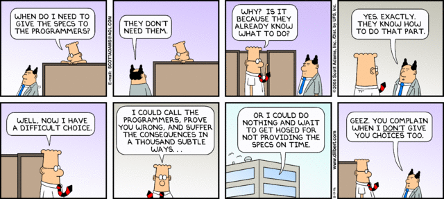
Agile methodologies prefer working code and direct communication over documentation. But in distributed teams it's impossible to rely only on direct conversations. Sometimes a bit of written specification is very helpful.

Informal specification

Primary documentation format for our projects is HTML (optionally connected with CmsWiki). Important benefits:

  • simple
  • known by web applications developers
  • portable (scales well from full-featured web browsers to simple handhelds)
  • many WYSIWYG editors available (including OpenOffice)

Alternate documentation format is RST (ReStructuredText). Important benefits:

  • simple like ASCII documents (minimal markup)
  • easy embedding of software code listings
  • easy convertable to other formats
  • mergable (two persons working on one file)

Sample of RST syntax:

Section title
=============

This is paragraph with some text *bolded out*. It's a link: http://aplikacja.info

 - A list
 - Another list item

Accepted variation of RST is use of Wiki. Benefits of this option:

  • document can be developed and inspected on-line (possibly in real-time with customer)
  • it's very easy to add changes (no need to update/checkin cycle to version control system)

Another very useful documentation format is spreadsheet. It's very easy to create (I recomment Google Docs for this task) and could be exported to CSV format in order to be parsed (testing/code generation purposes).

Formal specifications

For documenting existing software interfaces it's best to use automatically generated from source docs (Java Doc for Java, PyDoc for Python). They are always up-to-date because are regenerated automatically. JavaDoc example:

/**
 * Function description
 * @author DCI
 * @see AnotherClass.anotherMethod()
 **/
void loadTransactions(String filePath);

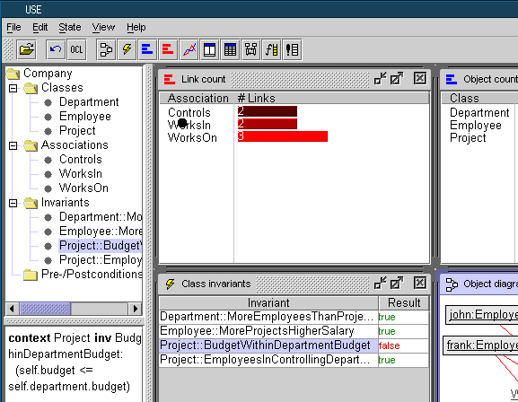
At more formalized level one can specify system using models (UML/OCL for instance). Those models can describe formally requirements and could be checked internally for consistency. I prefer open source tool called USE (A UML-based Specification Environment).

qt7

Writing system that will meet user requirements is as important as writing system correctly (with minimal bug rate). Transferring specification from users to development team is very important part of any project. Proper tools used for documentation may help here.

Tags: design.
Thu, 08 Dec 2011 23:55:36 +0000

I don't get UML designers. They skipped in UML very useful design tool: data flow diagrams (DFD) and placed cheap substitute called "activity diagram". Why? Because data flow is not object oriented (no encapsulation). Should we skip this useful tool and use only diagrams defined by UML? I don't think so.

On the other hand general problem with DFD (and any diagramming technique) is scalability. If you want to express many flows using DFD you have to make DFD hierarchical, thus overall picture may be hidden here. If you place too many (>9 items) details on one diagram you are lost again.

There's simple and very powerful, but forgotten technique called "CRUD tables". What's "CRUD"? It's a table (can be implemented by a spreadsheet) that for every process in a system defines it's interactions with main entities: Create, Read, Update, Delete. CRUD table was used mainly during database design, but I think this technique can be used for every data flow in a system (including external actors and entities).

I'll show you how you can utilize CRUD table to make initial design and get software complexity estimation.

First of all, a specification:

I need to sell products on my website. I'd like an order is created in my ERP system just after instant payments are finished.
Pretty short, but let's start design!

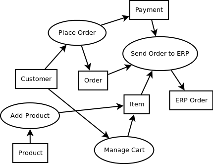
We can see how basic processes interacts with internal data (Product, Order, Item) and external entities (Payment, ERP Order). Let's check first rule:

Every process should have at least one input (R) and one output (CUD)
We can see rule is not valid for few processes, so let's add some Entities to fulfill this rule:

As you can see we added actor (Customer) to be a source (trigger) for some processes.

Now we can add estimation part. First: for every entity we can add complexity (we know that one entities can be more complicated than another), complexity of processes will result from used entities complexity:

Formula used for computation of "complexity" column:

=counta(C3)*$C$2+counta(D3)*D$2+counta(E3)*E$2+counta(F3)*F$2+counta(G3)*G$2+counta(H3)*H$2

So we know now that more complicated process will be sending order to an ERP system. If we added proper weights to operations (CRUD) and measure single activity we could estimate full effort needed to implement specified system.

Above CRUD translates into the following DFD:

I'd like to hear about your experience with CRUD modeling.

Tags: design, estimation.
Mon, 26 Oct 2015 21:10:50 +0000

One picture is worth of thousand words. So true. Even if you describe some flow with many detailed paragraphs one sequence diagram might show the idea instantly to the reader much better than all the words.

Separation of diagram drawing software (Visio, Dia, ...) from your main documentation system (Google Docs, Latex, doxygen, ...) is not a good idea. Having no access to source of the diagram makes modification much harder to do (when original author is not available, you have, actually, re-draw the diagram from scratch to fix some minor change).

Text-based diagrams and some form of post-processing is the answer to above problem. You embed your documentation AND the diagrams in the document and tools change those into graphics when needed. Example of such systems cooperation is doxygen and plantuml.

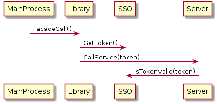
Let's see how easy sequence diagram could be expressed in plantuml:

@startuml{sequence.png} MainProcess -> Library: FacadeCall() Library -> SSO: GetToken() Library -> Server: CallService(token) Server -> SSO: IsTokenValid(token) @enduml

The result is rendered as diagram below:

sequenceThere are more advanced functionality there, but I hope you have already caught the idea.

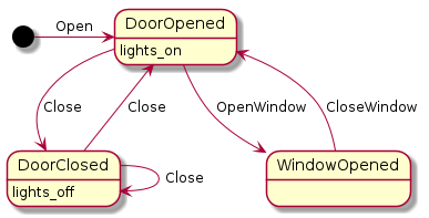
Next diagram type I'd like to explore is state diagram:

@startuml{state.png} [*] -right-> DoorOpened: Open DoorOpened -down-> DoorClosed: Close DoorClosed --> DoorOpened: Close DoorOpened --> WindowOpened: OpenWindow WindowOpened --> DoorOpened: CloseWindow DoorClosed --> DoorClosed: Close DoorOpened: lights_on DoorClosed: lights_off @enduml

The result looks like:

stateAs you can see you can leave positioning to automatic algorithm or specify manually some directions quite easily.

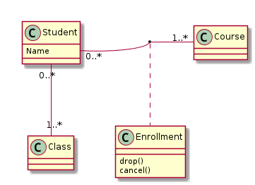
And what about class diagram? Sure! No problem!

@startuml{class.png} class Student { Name } Student "0..*" -right- "1..*" Course (Student, Course) . Enrollment Student "0..*" -- "1..*" Class class Enrollment { drop() cancel() } @enduml

And the result:

classQuite easy and intuitive!

Tags: design, uml.
Sun, 10 Jan 2016 00:34:02 +0000

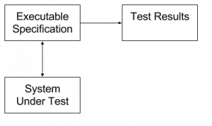
Executable Specification 1Executable specification is a "holly graal" of modern software engineering. It's very hard to implement as it requires:

  • Formal specification of rules
  • Transformation of those rules into real-system predicates
  • Stimulating system under tests state changes in repeatable manner

FitNesse is one of such approaches that specifies function sample inputs and outputs then allow to run such test cases using special connectors and provide colour reports from test runs. It's easy to use (from specification point of view), but has the following drawbacks:

  • Software architecture must be compatible with unit testing (what is very good in general: cut unnecessary dependencies, Inverse of Control, ...) - your current system might require heavy refactoring to reach such state
  • Rules are written and evaluated only during single test execution - different scenario requires another test case (no Design By Contract style continuous state validation)

Above features are present in any other unit test framework: JUnit, unittest, ... All such testing changes state and checks output.

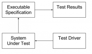
And now quite crazy idea has come to my mind: What if we forget about changing state and focus only on state validation? Executable Specification 2Then the executable specification won't be responsible for "test driver" job. Only state validation would be needed (including some temporal logic to express time constraints). That is much easier task to accomplish.

What about state changing then (the "Test Driver" role in the diagram) - you might ask? We have two options here:

  • random state changes to simulate global state machine coverage (randomtest.net)
  • click'n'play tools (which I hate, BTW) to deliver coverage over some defined paths (Selenium)
  • some API-level access to change system state and execute some interesting scenarios (system-dependant)

So let's go back to Specification then. Let's review some high level requirements (taken randomly from IPTV area) written in English and how they could be transformed into formal specification languages (I'm borrowing idea of "test tables" from FitNesse):

A requirement: video should be visible after device boot unless it's in "factory reset" state

Here we have the following state variables:

  • 1st_video_frame = true: detected by checking for special strings in decoder logs
  • device_boot = true: one could find unique entry in kernel log that shows device boot
  • factory_reset = true: missing some local databases state

Once parameters meaning has been specified by existence of log entries we could write the decision table here:

| device_boot | factory_reset | 1st_video_frame? | timeout | | true | false | true | 120s | | true | true | false | 120s |

As you might have noticed I've added extra parameter "timeout" that delivers the temporal part of the constraint. The meaning of this parameter is as follows: Given input condition is set the output condition should be met (even temporarily) in the timeout period

A requirement: the device should check for new software versions during boot or after TR-69 trigger, user might decide about the upgrade in both cases

Here we define the following state variables:

  • device_boot = true: the first kernel entry
  • check_software = true: proper log entry related to network activity for new software version retrieval
  • tr69_upgrade_trigger = true: local TR69 agent logs
  • user_upgrade_dialog = true: upgrade decision dialog visible

The decision table:

| device_boot | tr69_upgrade_trigger | check_software? | user_upgrade_dialog? | timeout | | true | - | true | - | 160s | | - | true | true | - | 30s |

(I use "-" as "doesn't matter" marker)

And here comes the hard part: we don't know whether new software is present for installation, so we cannot decide about user dialog. New property is needed:

  • new_sf_version_available

And the table looks like this:

| device_boot | tr69_upgrade_trigger | new_sf_version_available | check_software? | user_upgrade_dialog? | timeout | | true | - | true | true | true | 160s | | - | true | true | true | true | 30s | | true | - | true | false | false | 160s | | - | true | true | false | false | 30s |

We can see that table behaviour is a bit redundant there: we needed to multiply specification entries to show (tr69_upgrade_trigger x new_sf_version_available) cases.

However, above test will show failures when:

  • Despite the new version presence there was no software update dialog visible
  • No new version check has been triggered 160s after boot
  • ...

A requirement: rapid channel change should not exceed 600ms

This one looks a bit harder because of the low timeout and the usual buffering done on logs. However, having log flush interval limited to 100ms one can keep quite good performance and measure time with enough granularity.

Another caveat here is to exclude channels that are not available in current provisioning of the customer (you should see some up-sell page instead).

The states variable definition:

  • 1st_video_frame: specification as above
  • channel_up: P+ key has been pressed
  • channel_down: P- key has been pressed
  • channel_unavailable: system detects that current channel/event is not purchased yet

The specification:

| channel_up | channel_down | channel_unavailable | 1st_video_frame? | timeout | | true | - | false | true | 800ms | | - | true | false | true | 800ms |

Note that channel availability detection must be done at the same moment as channel change event - might be not true in most implementations (so not possible to reflect in our simple temporal logic language).

The implementation feasibility

In order above method to work it requires some kind of implementation.

  • System state changes detection: the output of a system could be serialized in single stream of textual events (redirected to serial line for embedded device, application server logs on server-based system)
  • Each interesting state variable changes could be derived from regexp parsing of above stream
  • On each state change all the collected rules would be examined to find active ones
  • The rules with timeout would setup a timeout callback to check the expected output state changes

The outputs of such test:

  • Failed scenarios with timestamp - for further investigation
  • Rules coverage - will tell you how good (or bad) your test driver is (how much coverage is delivered)

Based on first output you need to adjust your rules / matching patterns. Based on the second you should adjust your test driver policy.

It look like a feasible idea for implementation. I'm going to deliver a proof of concept in randomtest.net project.

RSS feed

Tags

Created by Chronicle v3.5